ULTRASONIC PULSE TESTING OF CONCRETE
Objective:
To Determine the Quality and the Dynamic Modulus of Elasticity of the Concrete Specimen using Ultrasonic Pulse Velocity method as per IS-516.
Apparatus used:
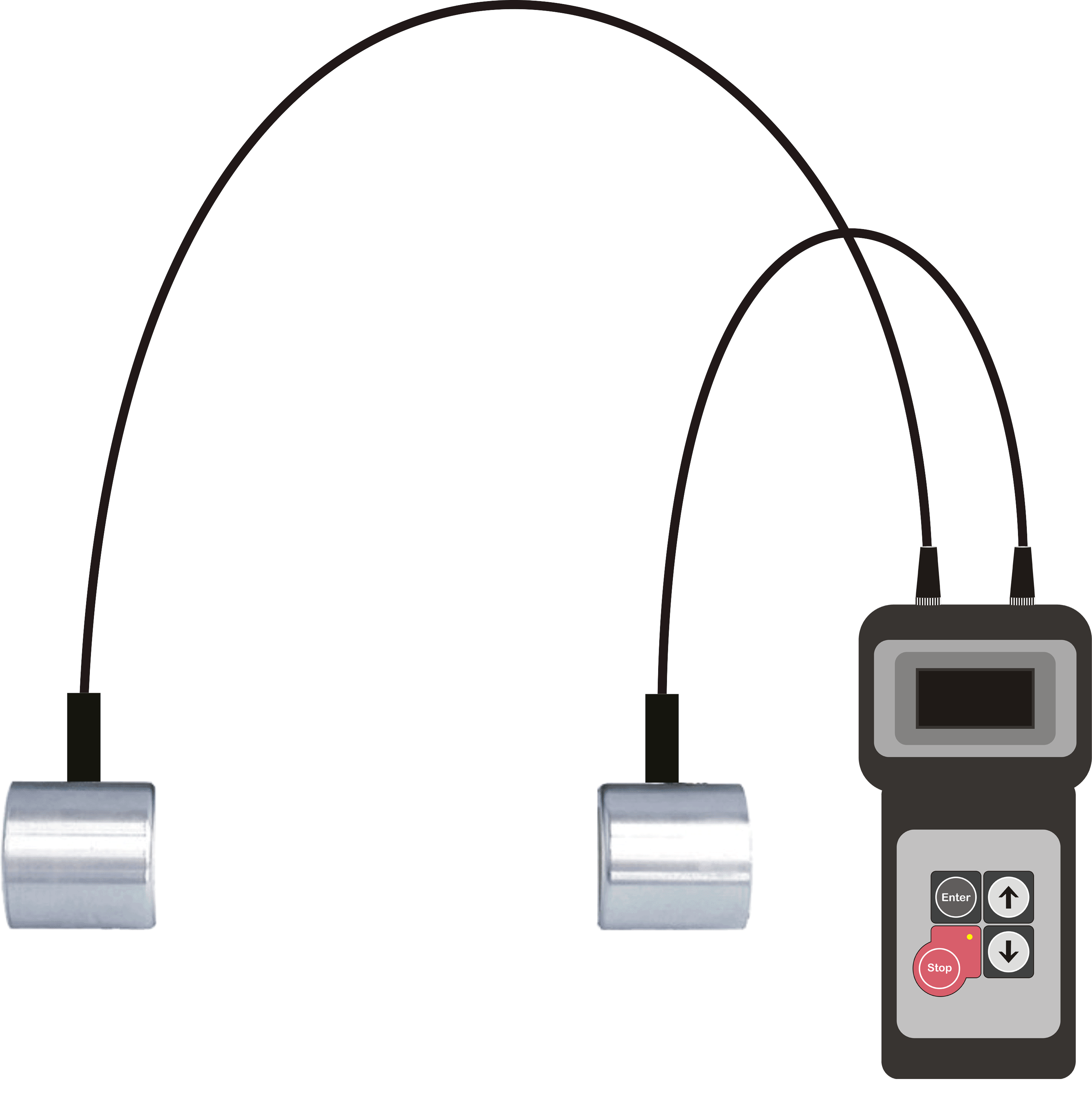
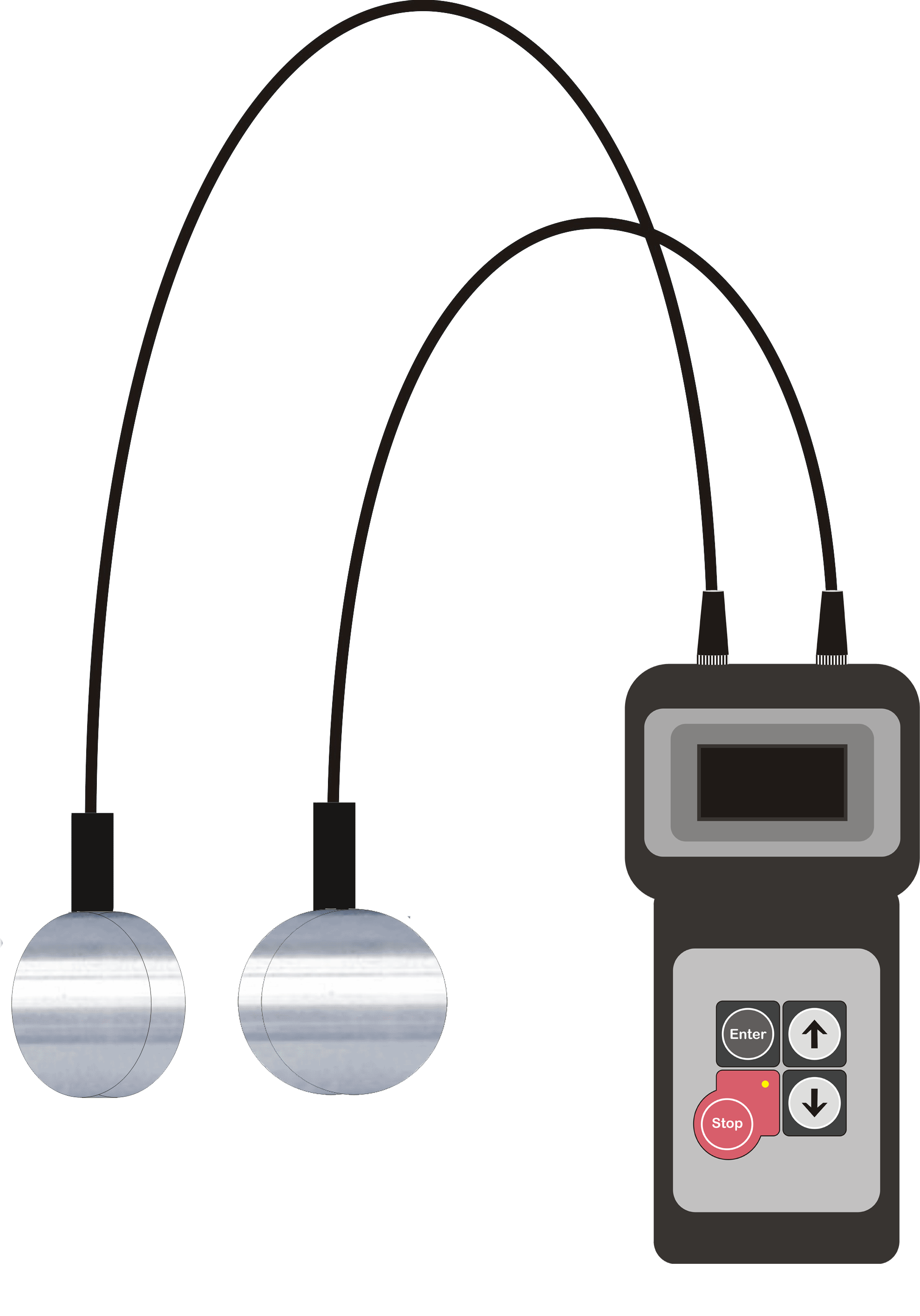
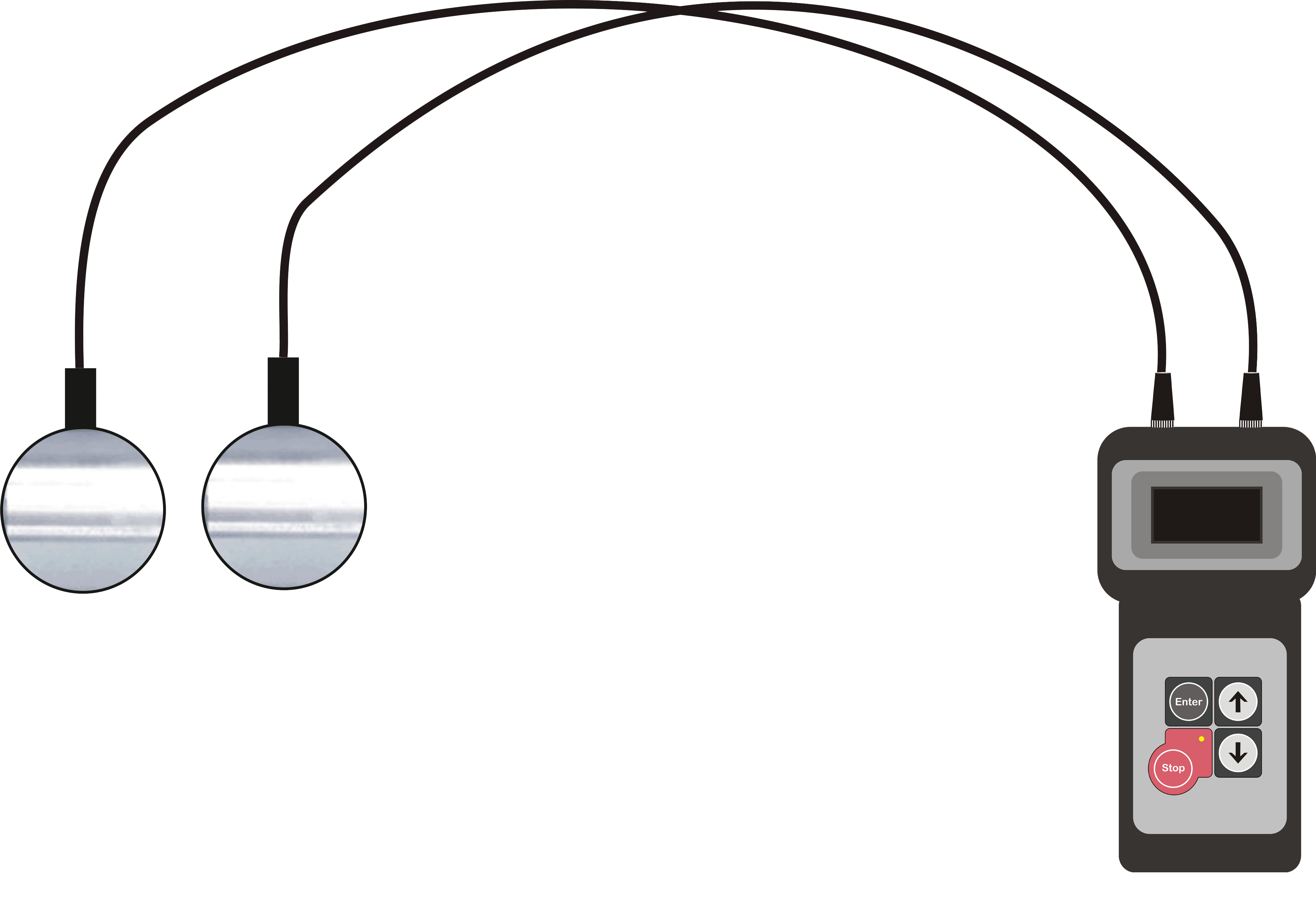
Transmitting Transducer, Receiving Transducer, Electronic Timing Device, Standard Calibration Bar, Carborundum Stone, Grease
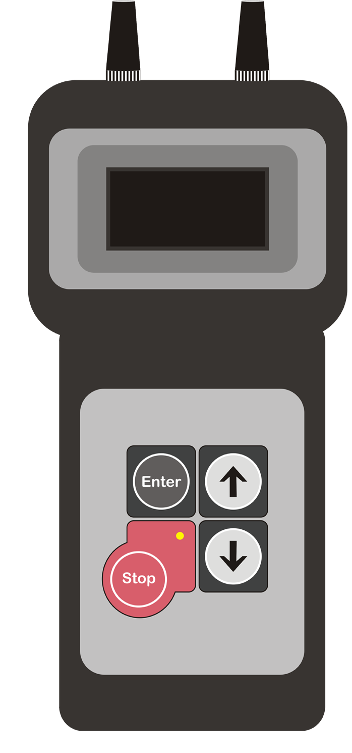
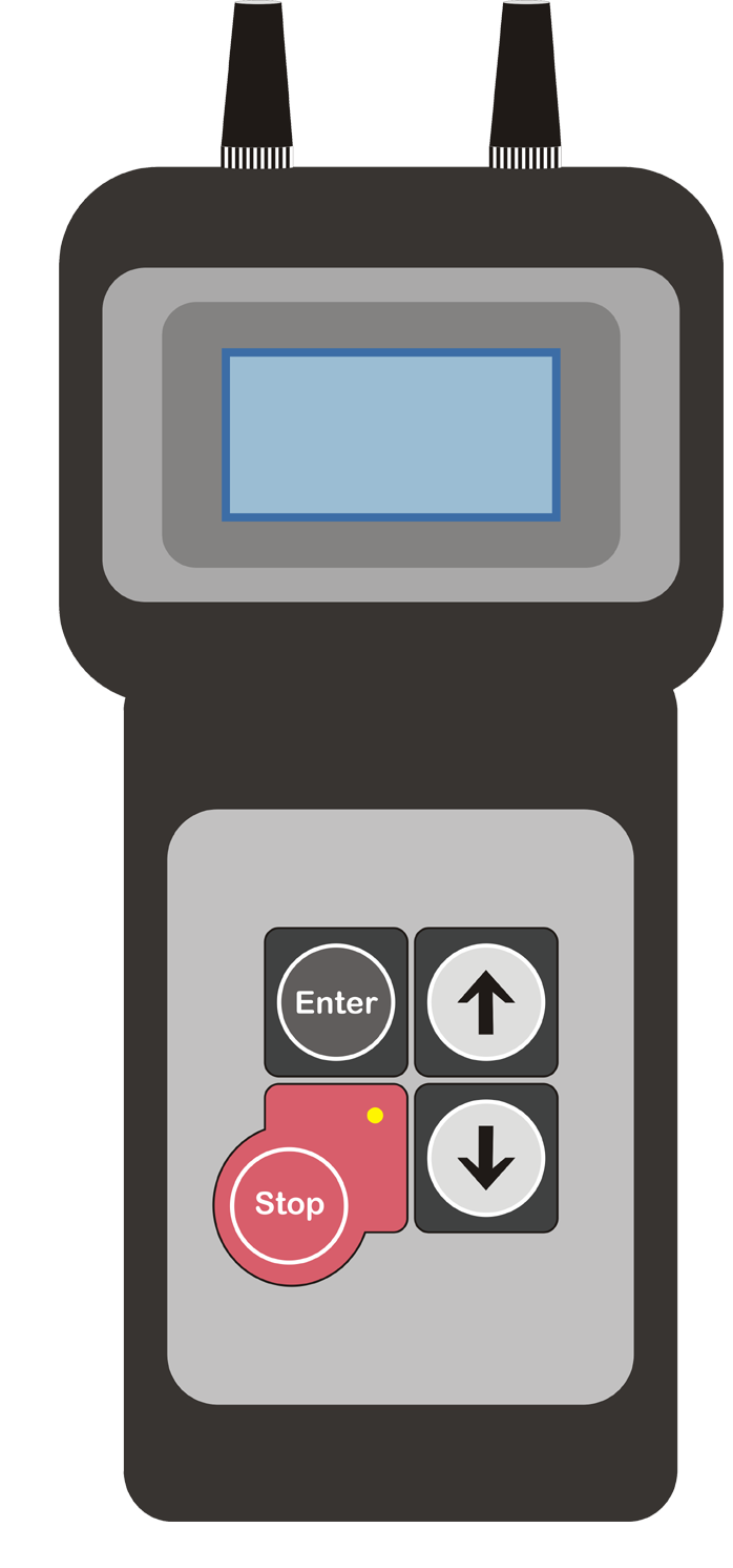
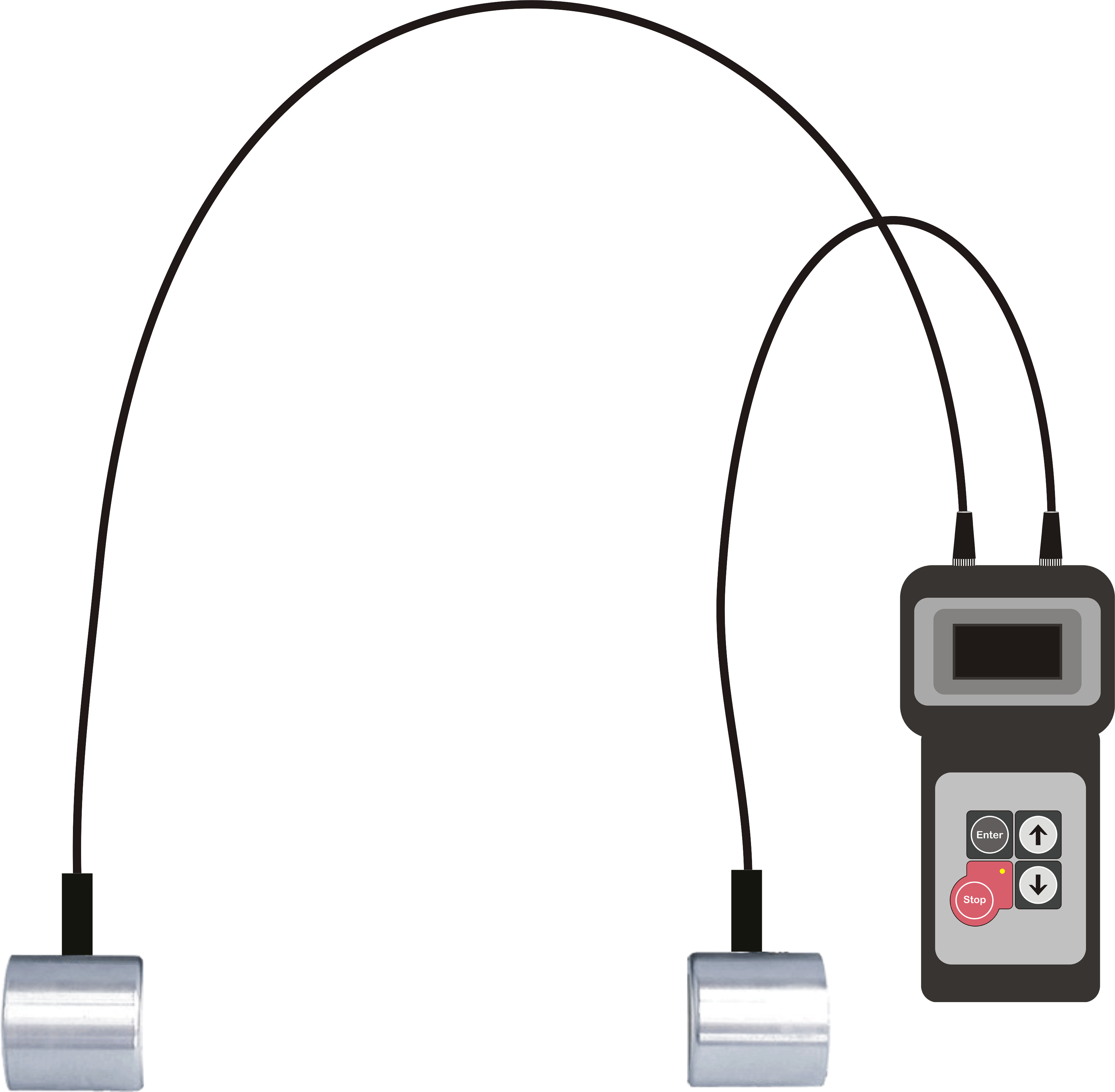 Electronic Timing Device
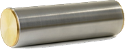 Calibration Bar
 Carborundum Stone
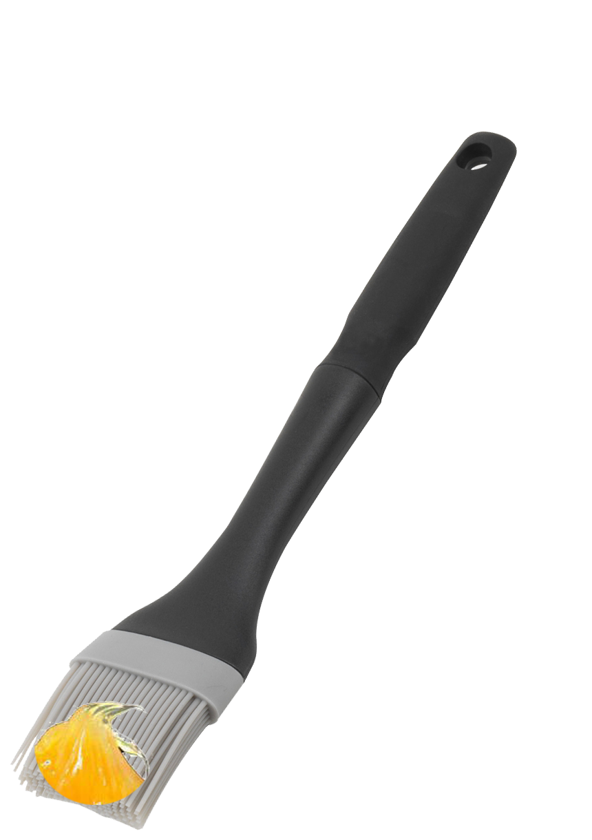
 Grease
 Transmitting
Transducer Receiving Transducer
Step 1: a). Click on Add Button to Add Electronic Timing Device
Step 1: b). Click on Add Button to Apply greese and the calibration bar.
Step 1: c). Click on Electronic Timing Device for Zoom View
Step 1: d). Click on Start Button on Electronic Timing Device to Power On it.
Step 1: e). Click on Stop Button on Electronic Timing Device to Power Off it.
Note: Transit time displayed on the device should be same as mentioned on the calibration bar, otherwise calibrate the device.

Select the Moisture Condition of Concrete.
Select the type of Transducer Arrangement.
DIRECT TRANSMISSION [ ]
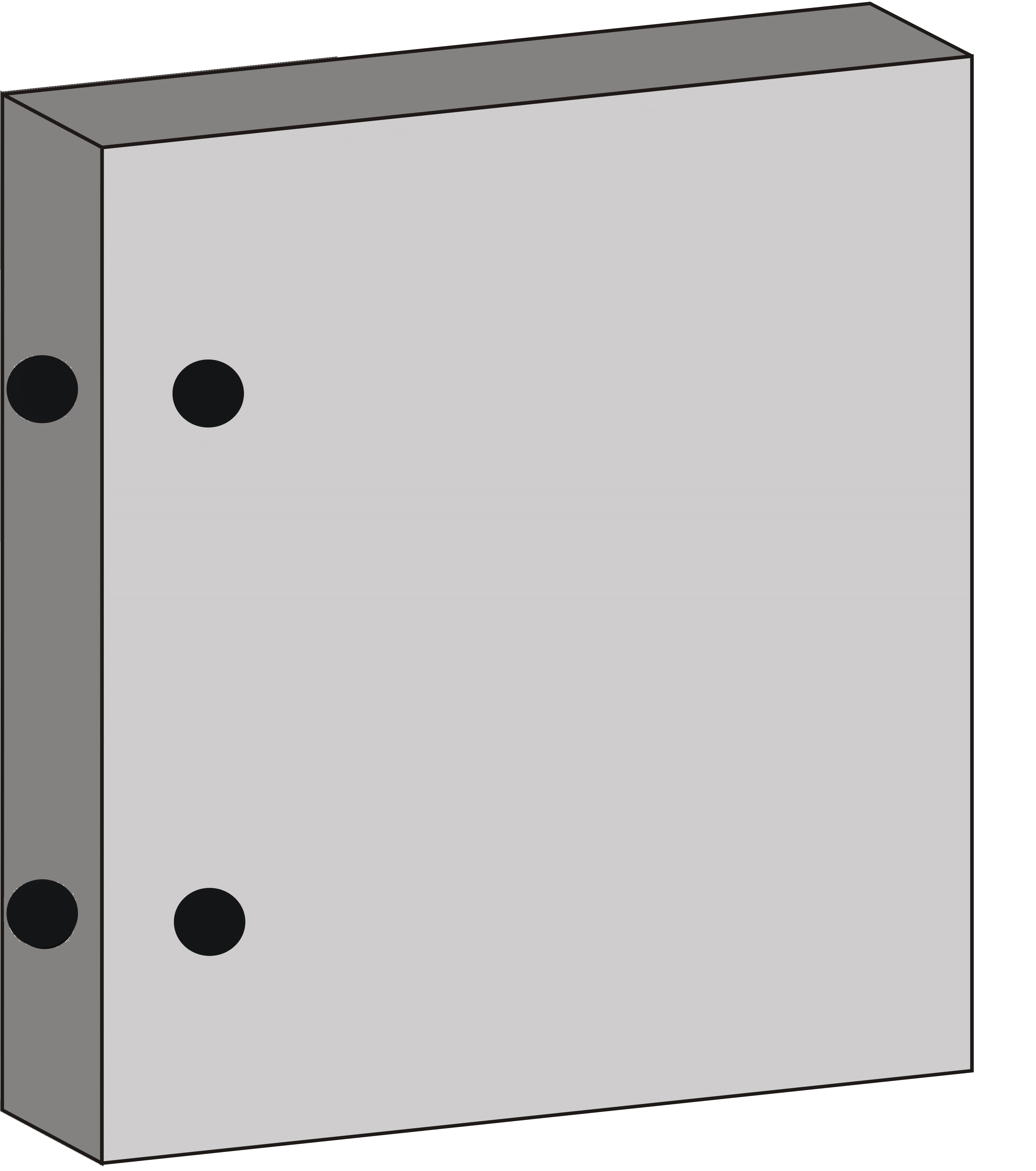
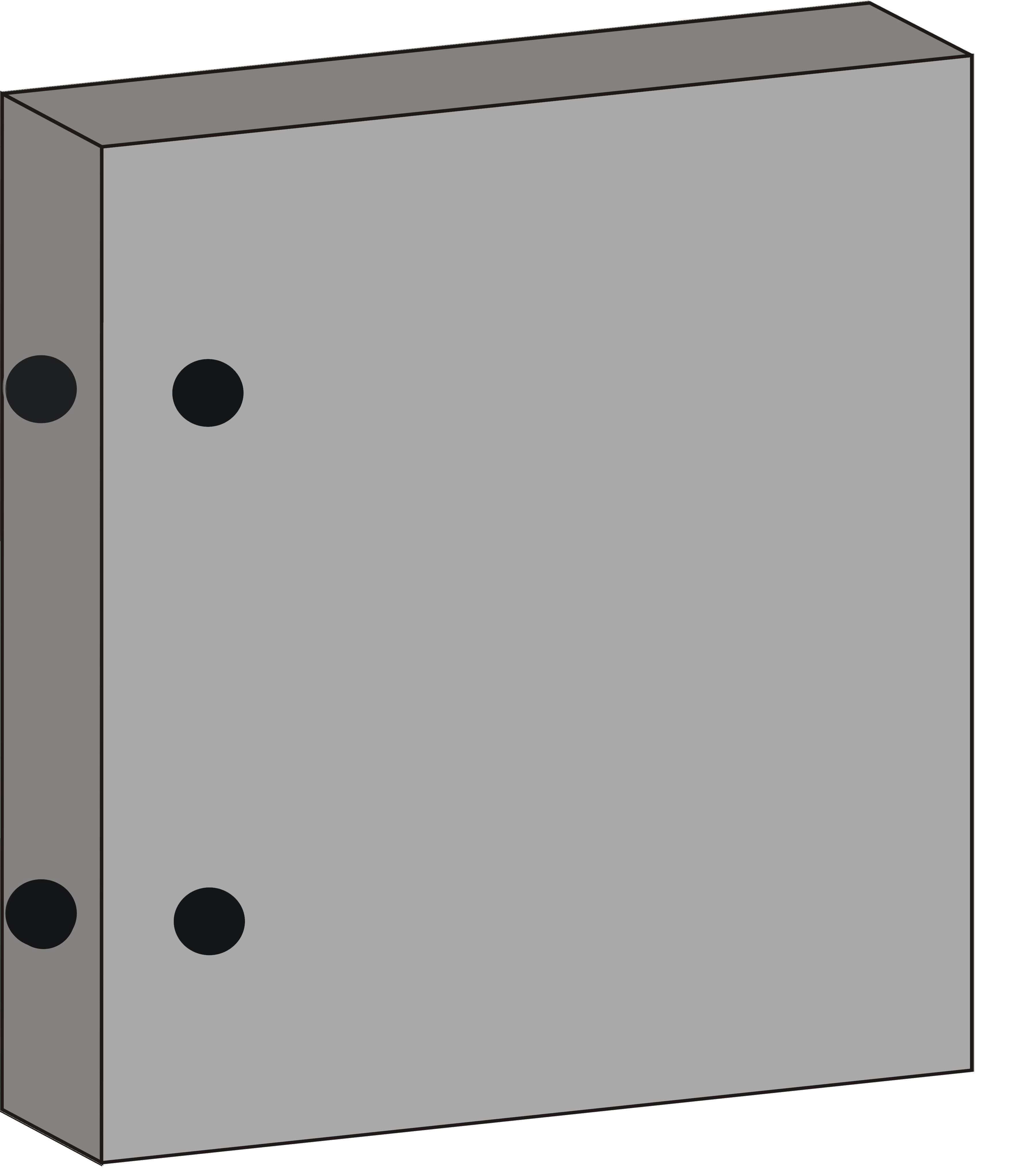
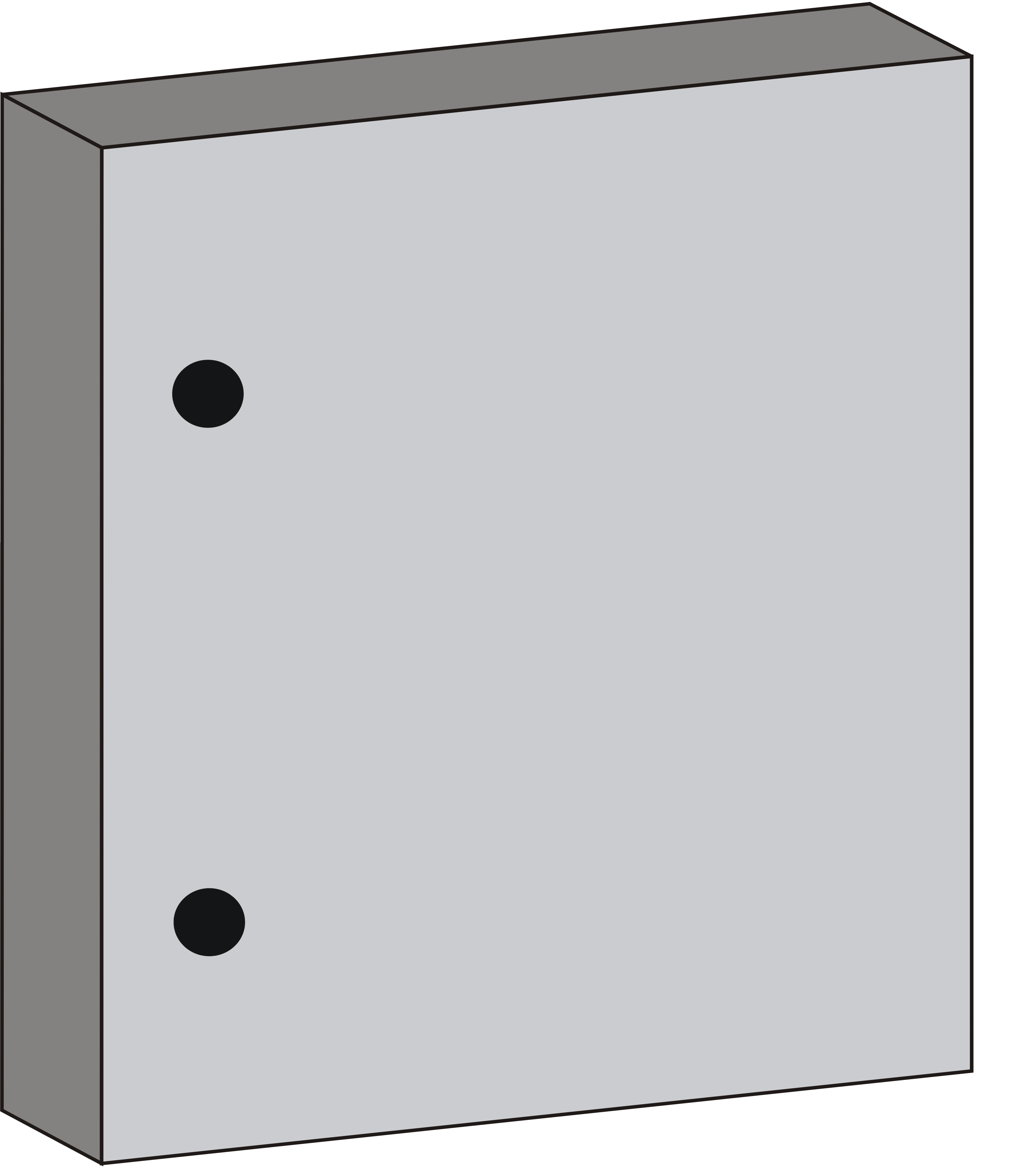
Step 2: a). Click on Add button to add a Marker and to mark the points on the specimens.
Step 2: b). Click on Marker for Mark Point A & Point B on the Wall.
Step 2: c). Again Click on Marker for Mark Point B on the Wall.
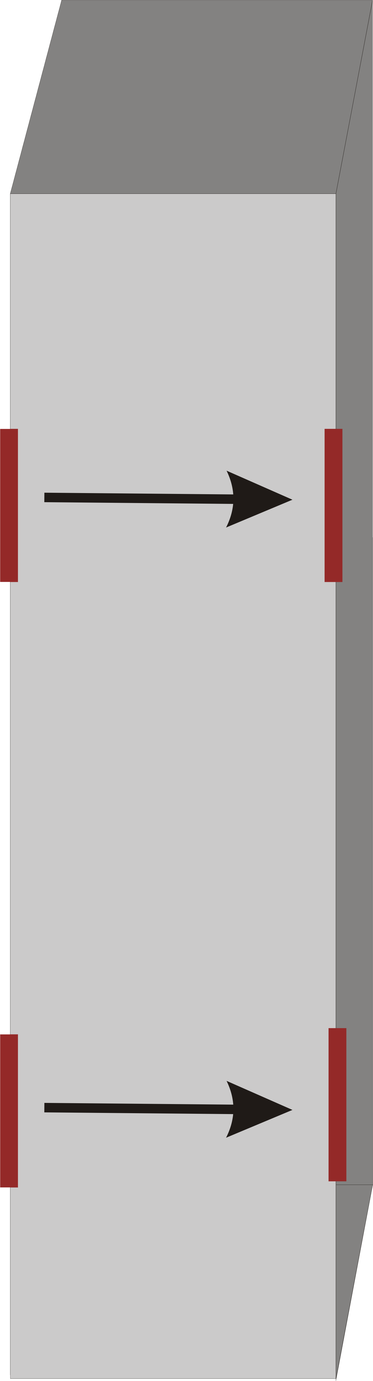
Step 2: c). Measure the path length.


DIRECT TRANSMISSION [ ]
Step 3: a). Click on Add button to Add Carborundum Stone.
Step 3: b). Click on Carborundum Stone for Removing Plaster or other Coating from the Marked Points.
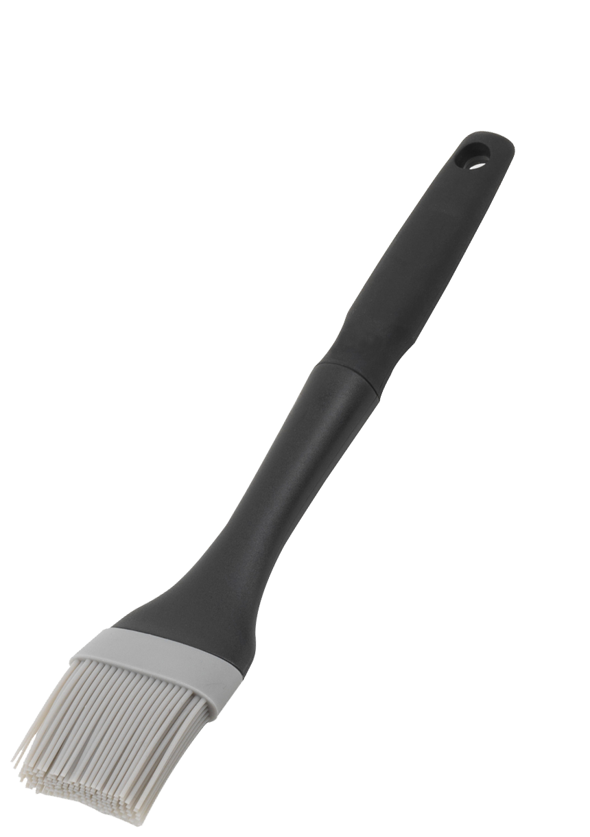
Step 3: c). Click on Add button to Add Grease Box.
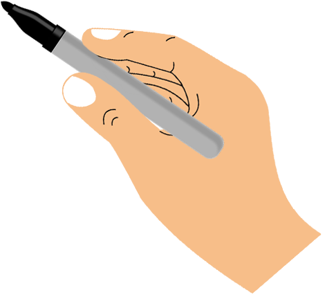
Step 3: d). Click on Brush for Greasing Marked Points.
Step 3: e). Again click on Brush for Greasing Marked Points.


DIRECT TRANSMISSION [ ]
Step 4: a). Click on Electronic Timing Device to Place the Transducer on the point A marked on the Wall.
Step 4: b). Click on Electronic Timing Device for Zoom View.
Step 4: c). Click on Start Button on Electronic Timing Device to Power On it.
Step 4: d). Click on Stop Button on Electronic Timing Device to Power Off it.
DIRECT TRANSMISSION [ ]
Step 5: a). Record the Path Length(L) of the Pulse= Width of the Wall.
b). Record the Time of Pulse Transmission for Three Times.
| Point |
Transmit time of the pulse(T), Micro-Second |
Path length(L)(mm) | Pulse velocity(V) (Km/s)=L/T |
| A | 107.3 | 0.302 | 2.82 |
| B | - | - | - |
| Average Time = | 2.82 | ||
DIRECT TRANSMISSION [ ]
Step 6: a). Click on Electronic Timing Device to Place the Transducer on the point B marked on the Wall.
Step 6: b). Click on Electronic Timing Device for Zoom View.
Step 6: c). Click on Enter Button on Electronic Timing Device to Power On it.
Step 6: d). Click on Stop Button on Electronic Timing Device to Power Off it.
DIRECT TRANSMISSION [ ]
Step 7: a). Record the Path Length(L) of the Pulse= Width of the Wall.
b). Record the Time of Pulse Transmission for Three Times.
| Point |
Transmit time of the pulse(T), Micro-Second |
Path length(L)(mm) | Pulse velocity(V) (Km/s)=L/T |
| A | 107.3 | 0.302 | 2.82 |
| B | 106.4 | 0.295 | 2.77 |
| Average Time = | 2.80 | ||
DIRECT TRANSMISSION [ ]
Observations: Calculate the average velocity
| Point |
Transmit time of the pulse(T), Micro-Second |
Path length(L)(mm) | Pulse velocity(V) (Km/s)=L/T |
| A | 107.3 | 0.302 | 2.82 |
| B | 106.4 | 0.295 | 2.77 |
| Average Velocity | 2.80 | ||
DIRECT TRANSMISSION [ ]
Results
| Sr.No. | Average Value of Pulse Velocity(V) | Concrete Quality Grading |
| 1 | 2.80 | N/A |
| 2 | 2.81 | N/A |
| Sr.No. | Path length(L)(mm) | Average transmit time of the pulse(T), Micro-Second | Pulse velocity(V) (Km/s)=L/T | Quality of Concrete | Dynamic Modulus of elasticity(E) (Kg/m/s2) |
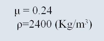
| 1 | 0.302 | 107.3 | 2.82 | N/A | 16192.76 |
| 2 | 0.295 | 106.4 | 2.77 | N/A | 15623.63 |
DIRECT TRANSMISSION [ ]
Report
| Set | Pulse velocity(V) (Km/s)=L/T | Quality of concrete | Dynamic Modulus of elasticity(E) (Kg/m/s2) |
| A | 2.82 | N/A | 16192.76 |
| B | 2.77 | N/A | 15623.63 |
SEMI-DIRECT TRANSMISSION [ ]
Step 3: a). Click on Add button to add Marker.
Step 3: b). Click on Marker for Mark Points on the Wall.
Step 3: c).Again Click on Marker for Mark Point B on the Wall.
 A
B
A
B
SEMI-DIRECT TRANSMISSION [ ]
Step 4: a). Click on Add button to Add Carborundum Stone.
Step 4: b). Click on Carborundum Stone for Removing Plaster or other Coating from the Marked Points.
Step 4: c). Click on Add button to Add Grease Box.
Step 4: d). Click on Brush for Greasing the Marked Points.
Step 4: e). Again click on Brush for Greasing the Marked Points.
SEMI-DIRECT TRANSMISSION [ ]
Step 4: a). Click on Electronic Timing Device to Place the Transducer on the point A marked on the Wall.
Step 4: b). Click on Electronic Timing Device for Zoom View.
Step 4: c). Click on Start Button on Electronic Timing Device to Power On it.
Step 4: d). Click on Stop Button on Electronic Timing Device to Power Off it.
SEMI-DIRECT TRANSMISSION [ ]
Step 5: a). Record the Path Length(L) of the Pulse= Width of the Wall.
b). Record the Time of Pulse Transmission for Three Times.
| Point |
Transmit time of the pulse(T), Micro-Second |
Path length(L)(mm) | Pulse velocity(V) (Km/s)=L/T |
| A | 107.3 | 0.302 | 2.82 |
| B | - | - | - |
| Average Time = | 2.82 | ||
SEMI-DIRECT TRANSMISSION [ ]
Step 6: a). Click on Electronic Timing Device to Place the Transducer on the point A marked on the Wall.
Step 6: b). Click on Electronic Timing Device for Zoom View.
Step 6: c). Click on Start Button on Electronic Timing Device to Power On it.
Step 6: d). Click on Stop Button on Electronic Timing Device to Power Off it.
SEMI-DIRECT TRANSMISSION [ ]
Step 7: a). Record the Path Length(L) of the Pulse= Width of the Wall.
b). Record the Time of Pulse Transmission for Three Times.
| Point |
Transmit time of the pulse(T), Micro-Second |
Path length(L)(mm) | Pulse velocity(V) (Km/s)=L/T |
| A | 107.3 | 0.302 | 2.82 |
| B | 106.4 | 0.295 | 2.77 |
| Average Time = | 2.80 | ||
SEMI-DIRECT TRANSMISSION [ ]
Observations: Calculate the average velocity
| Point |
Transmit time of the pulse(T), Micro-Second |
Path length(L)(mm) | Pulse velocity(V) (Km/s)=L/T |
| A | 107.3 | 0.302 | 2.82 |
| B | 106.4 | 0.295 | 2.77 |
| Average Velocity | 2.80 | ||
SEMI-DIRECT TRANSMISSION [ ]
Results
| Sr.No. | Average Value of Pulse Velocity(V) | Concrete Quality Grading |
| 1 | 2.80 | N/A |
| 2 | 2.81 | N/A |
| Sr.No. | Path length(L)(mm) | Average transmit time of the pulse(T), Micro-Second | Pulse velocity(V) (Km/s)=L/T | Quality of Concrete | Dynamic Modulus of elasticity(E) (Kg/m/s2) |
| 1 | 0.302 | 107.3 | 2.82 | N/A | 16192.76 |
| 2 | 0.295 | 106.4 | 2.77 | N/A | 15623.63 |
SEMI-DIRECT TRANSMISSION [ ]
Report
| Set | Pulse velocity(V) (Km/s)=L/T | Quality of concrete | Dynamic Modulus of elasticity(E) (Kg/m/s2) |
| A | 2.82 | N/A | 16192.76 |
| B | 2.77 | N/A | 15623.63 |
IN-DIRECT TRANSMISSION [ ]
Step 3: a). Click on Add button to add Marker.
Step 3: b). Click on Marker for Mark Points on the Wall.

 A
B
C
D
E
A
B
C
D
E
IN-DIRECT TRANSMISSION [ ]
Step 3: a). Click on Add button to Add Carborundum Stone.
Step 3: b). Click on Carborundum Stone for Removing Plaster or other Coating from the Marked Points.
Step 3: c). Click on Add button to Add Grease Box.
Step 3: d). Click on Brush for Greasing the Marked Points.
IN-DIRECT TRANSMISSION [ ]
Step 4: a). Click on Eletronic Timing Device to Place Transducer on Point A and Place Receiver at Point B.
Step 4: b). Click on Electronic Timing Device for Zoom View.
Step 4: c). Click on Start Button on Electronic Timing Device to Power On it.
Step 4: d). Click on Stop Button on Electronic Timing Device to Power Off it.
IN-DIRECT TRANSMISSION [ ]
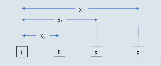
Step 5: a). Record the Time(T) of Pulse Transmission for Different Distance Between the Transducer
(Place the Transmitter at a Place the Receiver at C, then D and E).
|
Transmit time of the pulse(T), Micro-Second |
Distance between Transducers(mm) |
| N/A | N/A |
| N/A | N/A |
| N/A | N/A |
| N/A | N/A |
IN-DIRECT TRANSMISSION [ ]
Observations
|
Transmit time of the pulse(T), Micro-Second |
Distance between Transducers(mm) |
| N/A | N/A |
| N/A | N/A |
| N/A | N/A |
| N/A | N/A |
IN-DIRECT TRANSMISSION [ ]
Step 6: a). Plot the Graph (Best Fit Line) Between Pulse Transmit Time and the Distance
Between the Transducers.
IN-DIRECT TRANSMISSION [ ]
Results
| Sr.No. | Average Value of Pulse Velocity(V) | Concrete Quality Grading |
| 1 | 2.80 | N/A |
| 2 | 2.81 | N/A |
| Sr.No. | Path length(L)(mm) | Average transmit time of the pulse(T), Micro-Second | Pulse velocity(V) (Km/s)=L/T | Quality of Concrete | Dynamic Modulus of elasticity(E) (Kg/m/s2) |
| 1 | 0.302 | 107.3 | 2.82 | N/A | 16192.76 |
| 2 | 0.295 | 106.4 | 2.77 | N/A | 15623.63 |
IN-DIRECT TRANSMISSION [ ]
Report
| Set | Pulse velocity(V) (Km/s)=L/T | Quality of concrete | Dynamic Modulus of elasticity(E) (Kg/m/s2) |
| A | 2.82 | N/A | 16192.76 |
| B | 2.77 | N/A | 15623.63 |